
How Infrared Autofocus Systems Work And What to Look for When Specifying One
Published on:
Last edited:
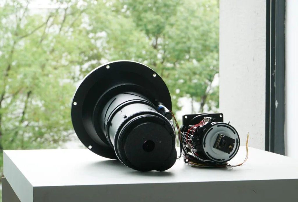
When a thermal camera maintains sharp focus through smoke, tracks a target from a moving vehicle, or operates reliably at -40°C, there’s a sophisticated autofocus system working behind the scenes. Understanding how these systems work helps engineers specify the right solution for their application.
1. Why Infrared Autofocus Is Different
If you’ve worked with visible-light cameras, you might assume infrared autofocus works the same way. It doesn’t—and the differences matter.
1.1 Material constraints
You can’t use conventional optical glass in the 8–12 µm LWIR band. Instead, infrared lenses use materials like germanium, zinc selenide (ZnSe), and chalcogenide glasses. Each has different refractive indices, dispersion characteristics, and thermal coefficients. Germanium, for example, has a high refractive index (~4.0) but significant thermal sensitivity—its focal length shifts measurably with temperature changes.
1.2 Detector differences
Infrared detectors operate on fundamentally different principles than silicon CMOS sensors. Uncooled microbolometers measure temperature-induced resistance changes; cooled photovoltaic detectors (InSb, HgCdTe) generate current from incident photons. The noise characteristics, frame rates, and signal processing requirements all differ from visible imaging.
1.3 Environmental demands
Many infrared applications involve harsh conditions—military vehicles, airborne platforms, outdoor security installations. The autofocus mechanism must maintain precision across wide temperature ranges while resisting vibration, dust, and moisture.
2. The Five Subsystems of an Infrared Autofocus Lens
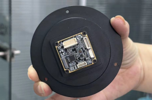
A well-engineered infrared autofocus system integrates five subsystems. Understanding each helps you evaluate specifications meaningfully.
2.1 The Lens Assembly
The optical train typically includes multiple lens groups—some fixed, some movable. The movable groups serve two functions: changing focal length (zoom) and adjusting the focus plane.
Here’s what many engineers don’t realize: in a continuous zoom lens, the relationship between zoom position and optimal focus position is non-linear. At 30mm, the best focus might be at one motor position; at 150mm, the optimal position isn’t simply a scaled version of that. The focus system must actively evaluate image quality across the zoom range rather than relying on precalculated lookup tables.
Front element coatings matter too. Diamond-like carbon (DLC) coatings provide hardness and durability while maintaining good transmission in the LWIR band. For field applications where the optic faces sand, salt spray, or cleaning abrasion, DLC significantly extends service life.
2.2 The Infrared Detector
The detector converts thermal radiation into electrical signals that the rest of the system can process. For mid-range systems, a common configuration is 640 × 512 pixels with 17 µm pixel pitch.
Why does this matter for autofocus? The detector’s noise floor directly impacts how reliably the focus algorithm can assess image sharpness. If detector noise is high relative to scene contrast, the algorithm struggles to distinguish “slightly out of focus” from “in focus but noisy.” Higher-quality detectors with better noise equivalent temperature difference (NETD) make autofocus more reliable, especially in low-contrast thermal scenes.
2.3 The Autofocus Algorithm
This is where the system’s intelligence lives. The algorithm answers a simple question: “Is the current image sharper than before?”
Most infrared autofocus systems use contrast detection methods. The principle: a well-focused image contains higher spatial frequencies than a defocused one. Sharp edges produce rapid intensity transitions; blurred edges produce gradual ones.
The algorithm computes a sharpness metric—often based on gradient magnitude, Laplacian variance, or frequency-domain energy—for each frame. It then drives the focus motor to maximize this metric.
The challenge is speed. To support real-time operation, the algorithm must evaluate each frame in milliseconds. This is why serious implementations run on FPGA hardware rather than general-purpose processors. An FPGA can perform the necessary convolutions and summations in parallel, achieving the throughput needed for 30+ fps operation.
Search strategy also matters. A naive approach might scan through the entire focus range looking for the peak—slow and power-hungry. Smarter algorithms use hill-climbing or golden-section search methods to converge quickly, typically finding optimal focus in under a second.
2.4 The Drive Mechanism
Knowing where to focus is half the problem. The system must physically move lens elements to that position—quickly, accurately, and repeatably.
The motor choice involves trade-offs. Stepper motors offer precise positional control but can introduce vibration and consume more power. DC motors with encoder feedback provide smooth motion but require more complex control loops. Piezoelectric actuators offer speed and precision but at higher cost.
The mechanical transmission—gears, lead screws, or direct drive—must minimize backlash. Any play in the drivetrain translates directly to focus uncertainty. If the algorithm commands a 10 µm movement but backlash absorbs 5 µm, focus accuracy suffers.
For zoom lenses, another consideration is optical axis consistency during zoom. As the zoom motor moves lens groups, does the image center shift? Even a few pixels of shift can be problematic for tracking applications. Well-designed systems specify this parameter explicitly.
2.5 The Mechanical Structure
All subsystems mount within a mechanical structure that must maintain precise alignment under real-world conditions.
Barrel construction typically uses aluminum for its strength-to-weight ratio and machinability. The challenge: aluminum’s thermal expansion coefficient differs from that of the optical materials. Over a -40°C to +80°C operating range, dimensional changes are significant. The mechanical design must accommodate this through material selection, flexure mounts, or athermalization strategies.
Environmental sealing protects internal components. IP67-rated front elements can withstand temporary immersion and resist dust ingress. For systems deployed in desert, maritime, or tropical environments, this isn’t optional.
Surface treatment affects both durability and thermal management. MIL-spec anodizing (MIL-A-8625) provides corrosion resistance and a matte finish that minimizes stray reflections.
3. Wavelength’s 30–150mm Motorized LWIR Zoom Lens
We designed this system for applications requiring continuous zoom with real-time autofocus: vehicle-mounted observation, airborne pods, urban security, and industrial thermal monitoring.
| Parameter | Specification |
|---|---|
| Focal Length | 30 mm – 150 mm continuous zoom |
| Working F/# | f/0.85 (wide) / f/1.2 (tele) |
| Field of View | 20.5° × 15.5° (wide) to 4.1° × 3.3° (tele) |
| Distortion | ≤ 12.5% (wide) / ≤ 1.5% (tele) |
| Wavelength Range | 8–12 µm |
| Compatible Detector | 640 × 512, 17 µm pitch |
| Zoom Axis Consistency | ≤ 3 pixels |
| Back Focal Length | 20 mm |
| Image Circle | Φ13.93 mm |
| Imaging Range | 0.5 m – ∞ (wide) / 13 m – ∞ (tele) |
| Operating Temperature | −40°C to +80°C |
| Storage Temperature | −40°C to +80°C |
| Weight | < 3.2 kg |
| Barrel Material | Aluminum |
| Sealing | IP67 (front element) |
| Lens Coating | DLC |
| Surface Treatment | Matte black anodizing, MIL-A-8625 Type II Class 2 |
| Motor Cable Length | 150 mm |
| Lens Mount | Flange interface |
3.1 What These Specifications Mean in Practice
≤3 pixel zoom axis consistency — During a full 30-150mm zoom, the image center shifts by no more than 3 pixels. For tracking applications, this means your target stays in frame without requiring pan/tilt compensation during zoom.
−40°C to +80°C operation — This covers the full military temperature range without requiring external heating or cooling. The optical and mechanical design maintains focus across this span.
IP67 front element — The system can operate in rain, snow, and dusty environments. Field maintenance doesn’t require clean-room conditions.
DLC coating — The front element resists scratching and environmental degradation, extending operational life in demanding conditions.
20 mm back focal length — Sufficient clearance for most detector dewars and mounting configurations.
4. Choosing the Right System for Your Application
Not every application needs continuous zoom autofocus. Fixed focal length lenses are simpler, lighter, and less expensive. Manual focus systems work fine for static installations with stable scene distances.
But for applications involving variable range targets, moving platforms, or remote/autonomous operation, motorized autofocus earns its complexity. The key is matching system capabilities to actual requirements—neither over-specifying (paying for capabilities you won’t use) nor under-specifying (discovering limitations after deployment).
Wavelength Opto-Electronic designs and manufactures precision infrared optics for demanding applications. For technical discussions about your infrared imaging requirements, contact our engineering team.
