
What are Acousto-Optic Deflectors? All About AODs Explained
Author: Bryan Ng – Marketing Manager
Published on:
Last edited:

Acousto-optic deflectors (AODs) are essential components in modern optical systems, offering high-speed, precise beam steering capabilities. These devices exploit the interaction between sound waves and light in a medium, typically a crystal, to diffract and control the direction of laser beams. AODs are widely used in laser scanning, optical communication, biomedical imaging, quantum optics, and material processing. This article explores the working principles, key parameters, applications, advantages, limitations, and selection criteria of AODs, providing a comprehensive overview of their role in photonics.
1. Principles of Acousto-Optic Deflection
AODs utilize the acousto-optic effect, a fundamental interaction between sound waves and light waves within a transparent medium such as quartz, tellurium dioxide (TeO₂), or fused silica. When an acoustic wave travels through the crystal, it induces a periodic modulation of the refractive index due to the photoelastic effect. This modulation behaves as a moving diffraction grating, which interacts with incident light in a highly controlled and tunable manner.
1.1 Diffraction Mechanism

When a coherent light source, typically a laser beam, enters the acousto-optic medium, it encounters this dynamic, sound-induced diffraction grating. Depending on the frequency and amplitude of the acoustic wave, the grating diffracts the incident beam at an angle determined by the phase-matching conditions of the light and sound waves.
2. Components and Construction

An AOD is a carefully engineered optoelectronic device designed to enable fast and precise deflection of laser beams using sound waves. It is composed of several critical components that work together to exploit the acousto-optic effect with high efficiency and reliability.
2.1 Acousto-Optic Crystal
At the core of the AOD is the acousto-optic crystal, a transparent medium through which both the optical and acoustic waves propagate. The choice of material is crucial and depends on the desired optical wavelength, acoustic velocity, diffraction efficiency, and power-handling capabilities.
Common materials include:
- TeO₂: Highly birefringent with excellent acousto-optic figure of merit; ideal for visible to near-infrared wavelengths; offers high diffraction efficiency at relatively low RF power.
- Fused Silica: Low acoustic attenuation and broad optical transparency; suitable for high-power applications but with a lower acousto-optic efficiency.
- Quartz: Offers good thermal stability and is often used in ultraviolet or IR applications.
The crystal is precision-cut along specific crystallographic axes to optimize acoustic wave propagation and phase matching with the optical beam. It is also typically anti-reflection (AR) coated on the input and output facets for specific laser wavelengths (e.g., 532 nm, 1064 nm) to minimize Fresnel losses and maximize throughput.
2.2 Piezoelectric Transducer
A piezoelectric transducer is bonded to one end of the acousto-optic crystal. This component converts the input radio-frequency (RF) electrical signal into mechanical vibrations, generating an acoustic wave that travels through the crystal.
- The transducer is usually made from materials such as lithium niobate or PZT (lead zirconate titanate).
- The geometry and placement of the transducer determine the acoustic beam shape, mode of propagation (longitudinal or shear), and bandwidth of the deflector.
The quality of the transducer-crystal interface is vital for efficient acoustic coupling and low insertion loss.
2.3 RF Driver

The RF driver (also called an RF synthesizer or generator) provides the electrical signal that excites the transducer. It controls two key parameters:
- RF frequency: Directly determines the diffraction angle of the deflected light beam. By tuning the frequency, the beam can be steered over a continuous angular range.
- RF power (amplitude): Influences the strength of the refractive index modulation in the crystal, and thus the diffraction efficiency.
Advanced AOD systems may use programmable, frequency-agile drivers capable of fast frequency hopping or sweeping, allowing for dynamic beam steering in real time.
2.4 Optical Aperture
The optical aperture defines the clear aperture or interaction region through which the laser beam enters and interacts with the acoustic wave inside the crystal. It is generally rectangular in shape, matching the acoustic beam cross-section and ensuring uniform diffraction performance across the beam profile.
- The size of the aperture affects the angular resolution and beam quality.
- A well-designed aperture ensures minimal beam clipping and diffraction artifacts.
Some designs also include internal or external beam-shaping optics to match the input beam to the acoustic interaction region for optimal efficiency.
3. Surface Quality and Accuracy
The performance and precision of an AOD are determined not only by its internal components and construction, but also by its surface quality, optical alignment, and a set of key operating parameters. Together, these influence how accurately and efficiently the AOD can manipulate a laser beam.
3.1 Wavelength Compatibility
Each AOD is designed and optimized for a specific laser wavelength or narrow wavelength range. This optimization includes:
- Crystal selection and orientation based on optical transparency and acoustic properties at the given wavelength.
- Anti-reflection coatings are tuned to minimize surface reflections at the operating wavelength.
- Phase matching conditions (Bragg angle) tailored for optimal diffraction efficiency.
Using the AOD at a wavelength outside its design range may result in significant loss of diffraction efficiency, increased optical aberrations, and unwanted reflection or scattering.
3.2 Deflection Angle
The deflection angle refers to the total angular range over which the AOD can steer the laser beam. AODs can achieve deflection angles typically ranging from a few milliradians to several tens of milliradians. Larger angles require broader RF bandwidths or slower acoustic velocities.
3.3 Resolution
Resolution defines the number of discrete, addressable beam positions across the deflection range. It depends on:
- RF bandwidth (frequency sweep range),
- Optical beam diameter, and
- Interaction length in the crystal.
Higher resolution is desirable in applications like raster scanning or optical trapping, where finely spaced beam positions are needed. However, it requires a balance with diffraction efficiency and response time.
3.4 Bandwidth
The RF bandwidth is the range of radio frequencies over which the AOD can operate effectively. It directly affects:
- The deflection angle (larger bandwidth allows greater angular scanning),
- The number of resolvable spots (higher resolution),
- The design of the RF driver, which must generate stable, high-fidelity signals across this range.
Wideband AODs may require specially designed transducers and impedance matching networks to maintain consistent diffraction efficiency across frequencies.
3.5 Diffraction Efficiency
Diffraction efficiency is the proportion of incident optical power diffracted into the desired first-order beam. It is a key figure of merit and is influenced by:
- Acoustic power (higher power → higher index modulation),
- Interaction length (longer length → more energy transfer),
- Beam overlap and alignment,
- Material properties (photoelastic coefficients, attenuation).
Typical diffraction efficiencies for AODs range from 60% to over 90%, depending on the application and wavelength. Excess power may be absorbed or scattered, so thermal management and optical quality are critical.
3.6 Response Time
Response time is the delay between an RF frequency change and the corresponding change in the laser beam’s deflection angle. It is governed by the time it takes for the acoustic wave to fill the optical beam path within the crystal. Typical response times are in the range of 1 to 10 microseconds, enabling high-speed beam steering suitable for applications like real-time imaging, spectroscopy, or laser modulation.
3.7 Surface Quality
Although often overlooked, the optical surface quality of the acousto-optic crystal is essential for minimizing optical aberrations and back reflections. Parameters include:
- Surface flatness (typically λ/10 or better),
- Scratch-dig specifications (e.g., 20-10 per MIL-PRF-13830B),
- Low scattering and high transmission surfaces via precision polishing and AR coating.
Poor surface quality can lead to:
- Increased laser-induced damage risk,
- Scattering-induced noise in imaging systems,
- Reduced optical throughput.
4. AODs vs. Other Beam Steering Technologies
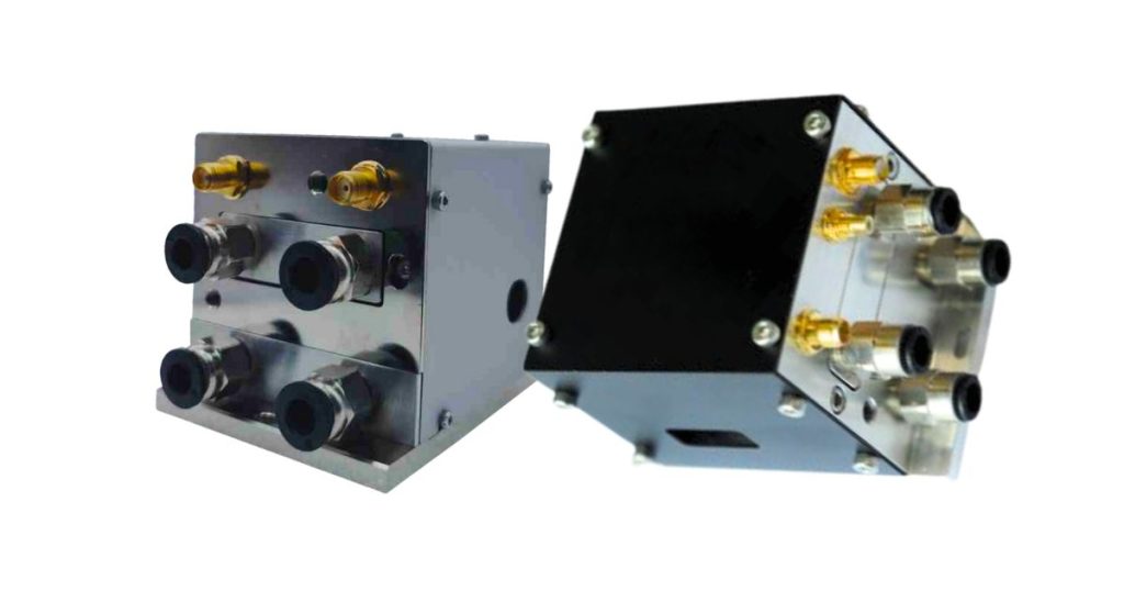
AODs are part of a broader family of beam steering technologies used to control the direction of laser beams in optical systems. Other commonly used methods include galvanometer mirrors, MEMS mirrors, and electro-optic deflectors (EODs). Each technology has its strengths and trade-offs in terms of speed, precision, size, range, and reliability.
4.1 Speed
One of the most significant advantages of AODs is their ultrafast response time, typically in the sub-microsecond to a few microseconds range. This rapid switching is due to the purely electronic nature of beam deflection, which relies on adjusting the RF signal applied to the transducer rather than physically moving components.
EODs: Similar or slightly faster than AODs (tens of nanoseconds) but with typically lower diffraction efficiency and limited angular range.
AODs: Response times in the nanosecond to low-microsecond range, making them ideal for high-speed applications like confocal microscopy, ultrafast spectroscopy, or quantum optics.
Galvanometer mirrors: Mechanical systems with response times in the millisecond range. Suitable for applications requiring large scan angles but not rapid beam switching.
MEMS mirrors: Micro-mechanical devices offering faster speeds than galvos (tens to hundreds of microseconds) but slower than AODs.
4.2 Reliability
AODs have no moving mechanical parts, making them highly reliable and robust against mechanical wear and vibration. This makes them suitable for long-term operation in industrial, space, or lab environments.
AODs: Long lifetime, minimal maintenance.
Galvanometers and MEMS mirrors: Mechanical motion introduces wear over time, requiring recalibration or replacement in high-duty cycles.
EODs: Also solid-state with no moving parts, but often more sensitive to alignment and environmental noise.
4.3 Precision and Resolution
AODs provide high angular resolution thanks to their continuous and highly controllable RF tuning:
- Fine deflection control is achieved by adjusting the acoustic frequency.
- The number of resolvable spots can be in the hundreds to thousands, depending on beam size and RF bandwidth.
In contrast:
- Galvanometer mirrors: Offer high positioning repeatability but are discrete in control and slower.
- MEMS mirrors: Provide moderate resolution but are limited by physical movement ranges and resonance frequencies.
- EODs: Very high-speed operation with low angular resolution unless used in complex configurations.
4.4 Deflection Angle and Optical Throughput
Despite their speed and precision, AODs have some inherent limitations:
- Deflection angle: Typically limited to a few degrees (a few tens of milliradians), which is significantly smaller than the tens of degrees achievable with galvanometers.
- Optical throughput: A portion of the incident beam is always lost due to the nature of diffraction. Even at high efficiency (~80–90%), the undiffracted zero-order beam carries residual power, which must be blocked or managed.
By comparison:
- Galvanometers: Offer large deflection angles (>20°), making them suitable for applications like wide-area laser projection or scanning.
- MEMS mirrors: Moderate deflection angles (±5° to ±15°).
- EODs: Also limited in angular range, similar to or smaller than AODs.
4.5 Summary
| Feature | AODs | Galvanometer Mirrors | MEMS Mirrors | Electro-Optic Deflectors |
|---|---|---|---|---|
| Response Time | Sub-microsecond | Millisecond | 10–100 µs | 10–100 ns |
| Deflection Angle | Small (≤ few degrees) | Large (up to 60°) | Moderate (±5°–15°) | Small (≤ few mrad) |
| Resolution | High (hundreds–thousands) | Moderate | Moderate | Low to moderate |
| Reliability | Very high (no moving parts) | Moderate (mechanical) | Moderate (micro-mechanical) | High (no moving parts) |
| Throughput | Moderate (with diffraction loss) | High | Moderate | Moderate |
| Best For | High-speed scanning, optical switching | Large-area scanning | Portable/miniature systems | Ultrafast switching |
5. Applications of AODs in Optical Systems
AODs have become essential components in modern photonic systems due to their fast response, fine angular control, and solid-state reliability. These characteristics enable a wide range of precision-demanding applications across scientific research, industrial processing, and emerging quantum technologies.
5.1 Laser Scanning and Imaging

One of the most widespread uses of AODs is in laser scanning systems, particularly in the biomedical and materials imaging sectors.
- Confocal Microscopy: AODs rapidly steer the excitation laser across the sample, enabling fast XY raster scanning. Their high scanning speed reduces photobleaching and allows real-time imaging of dynamic biological processes.
- Multiphoton Microscopy: The ability of AODs to scan without mechanical motion is especially valuable in multiphoton setups, where laser beam intensity must remain stable for deep-tissue imaging.
- Random-Access Scanning: Unlike traditional galvanometers, AODs can jump between any two scan points in microseconds. This enables targeted imaging of regions of interest, reducing acquisition time and phototoxicity.
- Flexible Field-of-View: Through RF frequency modulation, AODs support variable scan angles and zoom functions without physically moving the optics.
5.2 Optical Trapping and Manipulation

In optical tweezers and holographic manipulation, AODs serve as precise, dynamic tools to create and control light-based traps for microscopic particles.
- Multiple Trap Sites: By rapidly changing the diffraction frequency, AODs can steer the trapping laser beam between multiple points, effectively generating time-shared optical traps.
- Live Cell Manipulation: AOD-driven optical tweezers are used to move, sort, and rotate biological cells or organelles in real-time, enabling manipulation without physical contact.
- Particle Sorting and Force Spectroscopy: In microfluidics and colloidal physics, AODs allow programmable manipulation of particles based on size, refractive index, or behavior, offering highly flexible control.
5.3 Quantum Optics

Quantum experiments involving cold atoms, ions, and photons demand ultra-precise beam control, which AODs can deliver with nanoradian-scale accuracy.
- Atom Trapping and Addressing: In optical lattices or magneto-optical traps, AODs are used to focus laser beams on specific atoms or regions, allowing quantum state manipulation and selective cooling.
- Quantum Computing: AODs enable fast reconfiguration of optical control paths in trapped ion or neutral atom qubit systems, facilitating gate operations and qubit readout.
- Spatial Light Modulation: AODs modulate both the position and intensity of light beams used in quantum simulations, often in conjunction with spatial light modulators (SLMs).
- Low Cross Talk: The rapid and programmable nature of AOD deflection allows isolated addressing of individual quantum elements with minimal impact on neighboring regions.
5.4 Material Processing
AODs are increasingly applied in laser microfabrication, marking, and surface treatment, especially where precision and speed are critical.
- Beam Steering for Pattern Generation: AODs allow the laser to rapidly trace complex patterns on substrates without mechanical movement, ideal for high-resolution engraving, ablation, or deposition.
- Dynamic Focus Control: In conjunction with tunable lenses, AODs assist in 3D structuring and volumetric processing of materials like glass, polymers, and semiconductors.
- Ultrafast Laser Applications: AODs can steer femtosecond laser pulses with minimal dispersion, enabling precise energy delivery for clean cuts or sub-surface modifications.
5.5 LIDAR and 3D Imaging

With the growing demand for solid-state LIDAR and compact 3D sensing systems, AODs offer a non-mechanical alternative to traditional scanning methods.
No Wear and Tear: Compared to MEMS mirrors and rotating LIDAR systems, AODs provide robust performance with minimal drift over time.
Silent and Fast Scanning: AODs enable quiet, high-speed beam steering in automotive LIDAR, reducing acoustic noise and improving reliability.
Miniaturization: Their compact, solid-state design supports integration into portable sensing systems, such as drones, robots, and handheld devices.
Depth Imaging and TOF Systems: AODs can rapidly modulate beam direction for depth measurement in time-of-flight (TOF) 3D imaging systems, useful in navigation, mapping, and obstacle detection.
6. Advantages of Acousto-Optic Deflectors
AODs are widely favored in optical systems where speed, precision, and reliability are paramount. Their unique solid-state design and electronically tunable properties provide several distinct advantages over mechanical or MEMS-based beam steering methods.
6.1 High Speed
AODs offer exceptionally fast switching times, typically in the microsecond to sub-microsecond range.
- The time it takes to change the beam’s direction is determined by the time required for the acoustic wave to travel across the laser beam within the crystal—often just a few microseconds.
- This rapid response makes AODs ideal for real-time control, such as:
- High-speed laser scanning (e.g., in confocal microscopy)
- Dynamic trapping in optical tweezers
- Time-resolved spectroscopy and ultrafast optics
By eliminating the inertia of moving components, AODs outperform galvanometers and MEMS mirrors in applications where switching speed is critical.
6.2 High Precision
AODs provide fine angular control through continuous tuning of the RF drive frequency, enabling high angular resolution with smooth, jitter-free operation.
- Beam deflection angles are finely controlled by adjusting the acoustic frequency in small steps, often less than 1 MHz increments.
- This capability supports:
- Precise beam positioning in optical addressing systems
- High-resolution raster or vector scanning
- Controlled pattern generation in material processing
In many systems, AODs achieve hundreds to thousands of resolvable spots, depending on the aperture size and RF bandwidth.
6.3 Non-Mechanical Design
AODs operate without any moving mechanical parts, resulting in several operational and maintenance benefits:
- No mechanical wear or backlash, ensuring long-term stability and minimal drift.
- High reliability in environments prone to vibration, shock, or temperature variation.
- Minimal need for recalibration or component replacement, reducing downtime in industrial or lab systems.
This non-mechanical operation translates to higher uptime and lower total cost of ownership, particularly in continuous-use applications.
6.4 Compact Size
AOD modules are typically small and lightweight, making them easy to integrate into space-constrained optical setups.
- Their compact footprint supports integration in:
- Handheld or wearable devices (e.g., compact LIDAR or AR systems)
- Portable scientific instruments
- OEM modules in commercial scanning or metrology tools
Compared to bulky galvanometer-based systems, AODs enable miniaturization without sacrificing performance.
6.5 Flexible Operation
AODs support a wide range of modulation modes—both analog and digital—providing unmatched operational versatility:
- Analog beam steering: Smooth and continuous scanning by gradually varying RF frequency.
- Digital switching: Rapid jumps between discrete positions using digitally programmed RF signals.
- Amplitude modulation: AODs can also function as fast optical shutters or attenuators by controlling RF power.
This flexibility allows a single AOD to perform multiple roles within an optical system, from beam steering to intensity modulation to dynamic focusing.
7. Choosing the Right AOD
Selecting an appropriate AOD is crucial for achieving optimal performance in your optical system. Key factors to consider include:
7.1 Cooling Requirements
AODs generate heat during operation, especially at higher RF power levels. Effective thermal management ensures consistent performance and longevity.
- Thermal Load Assessment: Evaluate the expected RF power input and resultant heat generation.
- Heat Dissipation Methods: Implement appropriate cooling solutions, such as heat sinks or active cooling systems, to maintain optimal operating temperatures.
7.2 Laser Wavelength Compatibility
The AOD’s material must be compatible with your laser’s wavelength to ensure efficient diffraction.
- Material Selection: Different crystals (e.g., TeO₂, fused silica) have varying transparency ranges and acousto-optic figures of merit.
- Wavelength Matching: Ensure the chosen AOD material efficiently interacts with your specific laser wavelength.
7.3 Beam Diameter Considerations
The diameter of your laser beam affects both the resolution and the interaction time within the AOD.
- Resolution Impact: Larger beam diameters can enhance angular resolution but may require larger aperture AODs.
- Interaction Time: Beam diameter influences the acoustic transit time, affecting the device’s response speed.
7.4 Required Scan Angle
The desired deflection range dictates the necessary RF bandwidth and crystal dimensions.
- Bandwidth Needs: Wider scan angles require broader RF bandwidths to achieve the necessary frequency shifts.
- Crystal Size: Larger scan angles may necessitate larger crystals to accommodate the increased deflection range.
7.5 Application Specifics
Tailor your AOD choice to the specific demands of your application:
Material Processing: Consider power handling and durability.
Imaging: Prioritize high-speed scanning and resolution.
Optical Trapping: Focus on precise beam steering and stability.
8. Conclusion
AODs are indispensable tools in advanced optical systems. Their ability to steer beams rapidly and precisely without mechanical parts makes them ideal for a range of high-speed applications. While they come with some limitations, ongoing research and development continue to enhance their performance and broaden their application scope. Whether in scientific research, industrial automation, or next-generation imaging systems, AODs play a critical role in shaping the future of photonics.
Wavelength Opto-Electronic provides a comprehensive range of acousto-optic devices tailored to diverse applications:
- We offer AODs, AOMs, frequency shifters, and tunable filters, covering wavelengths from 266 nm to 10.6 μm.
- We’ve both free-space and fiber-coupled configurations, accommodating various system requirements.
- Depending on the crystal, wavelength, and beam size, our AODs achieve response times ranging from 0.05 to 15 μs and precise position control at the nanoradian level.
| Part Numbers | Wavelength | Active Aperture | Center Frequency | Bandwidth | Scan Angle | Material |
| AODF0003-QL230_110-020-266 | 266 nm | 2×26.5 mm | 230 MHz | 110 MHz | 5.1 mrad | Crystalline quartz |
| AODF0005-QL230_110-020-266 | 266 nm | 2×2 mm | 230 MHz | 110 MHz | 5.1 mrad | Crystalline quartz |
| AODF2005-QL200_100-020-266 | 266 nm | 2.0×26.5 mm | 200 MHz | 100 MHz | 4.6 mrad | Crystalline quartz |
| AODF2008-QL200_100-040-266 | 266 nm | 4.0×4.0 mm | 200 MHz | 100 MHz | 4.6 mrad | Crystalline quartz |
| AODF2001-QL170_070-070-355 | 355 nm | 7 mm | 170 MHz | 70 MHz | 4.3 mrad | Crystalline quartz |
| AODF2002-QL170_030-070-355 | 355 nm | 7 mm | 170 MHz | 30 MHz | 1.9 mrad | Crystalline quartz |
| AODF0006-QL110_16-060-364 | 364 nm | 6 mm | 110 MHz | 16 MHz | 1 mrad | Crystalline quartz |
| AODF2006-TS100_050-035-364 | 364 nm | 3.5 mm | 100 MHz | 50 MHz | 29.6 mrad | Tellurium dioxide |
| AODF2007-TS100_050-080-364 | 364 nm | 8 mm | 100 MHz | 50 MHz | 29.6 mrad | Tellurium dioxide |
| AODF0007-TS075_10-040-405 | 405 nm | 4 mm | 75 MHz | 10 MHz | 6.6 mrad | Tellurium dioxide |
| AODF0008-TS100_36-010-488 | 488 nm | 1 mm | 100 MHz | 36 MHz | 27.1 mrad | Tellurium dioxide |
| 2AODF2003-TS088_44-100-515 | 515 nm | 10× 10 mm | 88 MHz | 44 MHz | 34.9×34.9 mrad | Tellurium dioxide |
| 2AODF2001-TS085_40-100-532 | 532 nm | 10 mm | 85 MHz | 40 MHz | 32.4×32.4 mrad | Tellurium dioxide |
| AODF0009-TS100_36-010-561 | 561 nm | 1 mm | 100 MHz | 36 MHz | 30.04 mrad | Tellurium dioxide |
| 2AODF2002-TS100_42-075-813 | 813 nm | 7.5×7.5 mm | 100 MHz | 42 MHz | 52.5×52.5 mrad | Tellurium dioxide |
| AODF0010-TS090_30-025-1064 | 1064 nm | 2.5 mm | 90 MHz | 30 MHz | 48.2 mrad | Tellurium dioxide |
| AODF2003-TL075_32-025-1083 | 1083 nm | 2.5 mm | 75 MHz | 32 MHz | 8.3 mrad | Tellurium dioxide |
By carefully evaluating these factors and leveraging our expertise, you can select an AOD that aligns with your system’s performance goals and operational requirements.
