
UV Laser Optics: The Optics Behind Precision UV Laser Processing
Author: Bryan Ng – Marketing Manager
Published on:
Last edited:
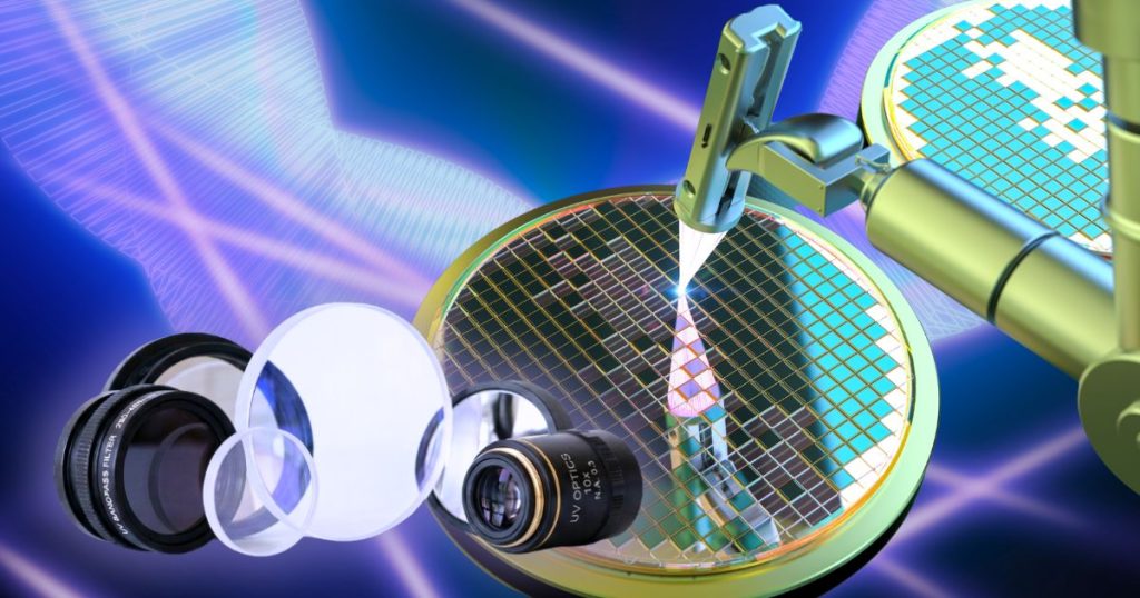
Ultraviolet lasers have become indispensable across semiconductor manufacturing, microelectronics, medical device fabrication, and advanced materials processing. Their short wavelengths — typically in the 193 nm to 405 nm range — allow for extremely fine focal spots, minimal heat-affected zones, and micron-level precision that longer-wavelength lasers cannot match. But a UV laser source is only half the story. The optics that transmit, shape, and focus that beam ultimately decide whether a system delivers clean, repeatable, high-quality results — or falls short on precision and lifetime.
This is the world of UV laser optics: a specialized category of optical components engineered to withstand the punishing combination of high photon energy, tight tolerances, and the demanding duty cycles imposed by UV wavelengths.
As UV lasers have moved from research labs into mainstream production lines — driving everything from smartphone component marking to flexible PCB drilling — the optics that support them have had to keep pace. What was once a niche specialty is now a core engineering discipline in its own right, with its own materials science, coating chemistry, and design conventions. Understanding how these components work and what separates a well-engineered system from a mediocre one is essential for anyone specifying or building UV laser equipment.
1. Why UV Laser Optics are a Different Engineering Challenge
Standard visible or infrared optics can’t simply be repurposed for UV applications. Shorter wavelengths carry more energy per photon, which means coatings and substrates must resist optical damage, UV-induced absorption, and solarization (a gradual darkening of glass under UV exposure) far more aggressively than their IR or visible-light counterparts. Material selection becomes critical — fused silica is typically favored over standard optical glass for its high UV transmission and superior laser damage threshold, while specialized anti-reflection and high-reflectivity coatings must be tuned precisely to narrow UV bands.
Because of these constraints, UV laser optics generally fall into three core categories, each solving a distinct part of the beam-delivery chain: focusing the beam onto a work surface, adjusting beam diameter and divergence, and redirecting the beam with minimal loss.
There’s also a practical reason UV laser optics command a premium over visible or IR counterparts: manufacturing tolerances are tighter across the board. Surface figure, coating uniformity, and cleanliness requirements all scale up as wavelength scales down, since microscopic contamination or sub-wavelength surface irregularities invisible to a 1064 nm beam can scatter or absorb a 355 nm beam enough to measurably degrade performance.
2. Common UV Wavelengths and Their Applications
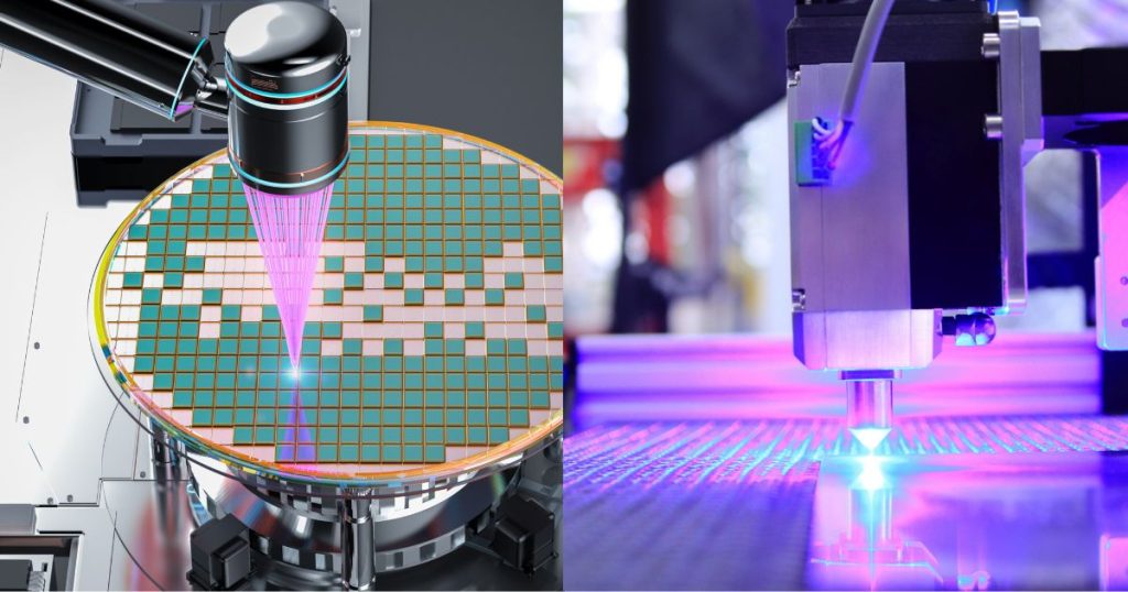
Not all UV is created equal, and the specific wavelength a system uses has real consequences for optics selection. A few of the most common industrial and scientific UV laser lines include:
- 193 nm (ArF excimer): Used primarily in semiconductor photolithography and precision micromachining where extremely fine feature sizes are required. Optics at this wavelength demand the highest-grade fused silica and specialized coatings, since very few materials transmit efficiently this far into the deep UV.
- 248 nm (KrF excimer): Common in laser annealing, thin-film patterning, and some medical device applications such as stent cutting.
- 257 nm and 266 nm: Frequency-quadrupled Nd:YAG/Nd:YVO4 outputs, widely used in high-resolution marking, wafer inspection, and fine-feature drilling.
- 355 nm: Frequency-tripled Nd:YAG, arguably the workhorse UV wavelength for industrial marking, engraving, and micromachining thanks to its balance of precision and available laser power.
- 405 nm: Sits at the visible-UV boundary and is used in applications like optical data storage, certain curing processes, and fine-detail imaging systems.
Each of these wavelengths interacts differently with coatings, substrates, and adhesives, which is why UV laser optics are typically specified — and manufactured — around a particular design wavelength rather than sold as generic, wavelength-agnostic components.
3. The Three Pillars of a UV Laser Optics System
3.1 UV F-Theta Scan Lenses
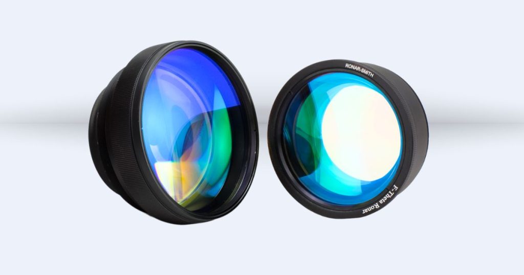
In galvanometer-based scanning systems used for laser marking, engraving, drilling, and cutting, an F-theta lens ensures the focused spot lands on a flat plane across the entire scan field — rather than curving off-axis, as a standard focusing lens would. Several variants address different application needs:
- Standard F-theta lenses deliver a tightly focused spot across the scan field and are the workhorse choice for marking and engraving systems.
- Telecentric F-theta lenses keep the beam perpendicular to the work surface at every point in the field, flattening field curvature and minimizing distortion — critical for applications where spot consistency matters as much as spot size.
- Achromatic F-theta lenses correct for chromatic aberration between the UV processing wavelength and a visible feedback wavelength, enabling machine-vision-guided processing without sacrificing beam quality.
- Achromatic telecentric F-theta lenses combine both benefits, supporting integrated vision inspection systems that need accurate positioning data without requiring the workpiece to be removed for offline inspection.
| Part Number | Wavelength (nm) | EFL (mm) | Scan Field (mm x mm) | Input Beam Dia (1/e2) (mm) | F-Theta (Standard or Telecentric) | Material | Mounting Thread | WD (mm) |
|---|---|---|---|---|---|---|---|---|
| SL-257.5-280-450Q-D14 | 257.5 | 450.0 | 280 x 280 | 14 | Standard | Fused Silica | M85x1 | 537.9 |
| SL-266-70-100Q | 266 | 100.0 | 70 x 70 | 5 | Standard | Fused Silica | M85x1 | 132 |
| SL-266-100-160Q | 266 | 162.3 | 100 x 100 | 5 | Standard | Fused Silica | M85x1 | 198.8 |
| SL-266-150-250Q | 266 | 250.0 | 150 x 150 | 4 | Standard | Fused Silica | M55x1 | 298.4 |
| SL-355-50-100-D10-LP | 343-355 | 100.0 | 50 x 50 | 10 | Standard | Optical Glass | M85x1 | 130 |
| SL-355-60-100Q | 343-355 | 100.0 | 60 x 60 | 6 | Standard | Fused Silica | M85x1 | 136.9 |
| SL-355-70-180Q-D12 | 343-355 | 180.0 | 70 x 70 | 12 | Standard | Fused Silica | M85x1 | 141.9 |
| SL-355-76-108Q | 343-355 | 108.0 | 76 x 76 | 6 | Standard | Fused Silica | M85x1 | 137 |
| SL-355-85-160Q | 343-355 | 160.0 | 85 x 85 | 10 | Standard | Fused Silica | M85x1 | 216.2 |
| SL-355-100-160Q | 343-355 | 160.0 | 100 x 100 | 7 | Standard | Fused Silica | M85x1 | 197.4 |
| SL-355-105-170Q | 343-355 | 170.0 | 105 x 105 | 6 | Standard | Fused Silica | M85x1 | 216.1 |
| SL-355-125-210-D10 | 343-355 | 210.0 | 125 x 125 | 10 | Standard | Fused Silica | M55x1 | 260 |
| SL-355-155-250Q | 343-355 | 250.0 | 155 x 155 | 10 | Standard | Fused Silica | M85x1 | 297.7 |
| SL-355-160-210Q-D12 | 343-355 | 210.0 | 160 x 160 | 12 | Standard | Fused Silica | M85x1 | 247.2 |
| SL-355-175-254Q | 343-355 | 254.0 | 175 x 175 | 12 | Standard | Fused Silica | M79x1/M85x1 | 304.9 |
| SL-355-180-295Q | 343-355 | 295.0 | 180 x 180 | 10 | Standard | Fused Silica | M85x1 | 359.6 |
| SL-355-210-330Q | 343-355 | 330.0 | 210 x 210 | 14 | Standard | Fused Silica | M85x1 | 265.1 |
| SL-355-250-360Q-D12 | 343-355 | 360.0 | 250 x 250 | 12 | Standard | Fused Silica | M85x1 | 418.1 |
| SL-355-320-580Q-D10 | 343-355 | 580.0 | 320 x 320 | 10 | Standard | Fused Silica | M85x1 | 671.5 |
| SL-355-330-511Q | 343-355 | 511.0 | 330 x 330 | 14 | Standard | Fused Silica | M85x1 | 606 |
| SL-355-350-580Q | 343-355 | 580.0 | 350 x 350 | 10 | Standard | Fused Silica | M85x1 | 682.8 |
| SL-355-400-580Q | 343-355 | 580.0 | 400 x 400 | 10 | Standard | Fused Silica | M79x1 | 677.6 |
| SL-355-400-580Q-D15 | 343-355 | 580.0 | 400 x 400 | 15 | Standard | Fused Silica | M85x1 | 652.3 |
| SL-355-440-830Q | 343-355 | 830.0 | 440 x 440 | 14 | Standard | Fused Silica | M85x1 | 979.1 |
| SL-355-470-920Q | 343-355 | 919.0 | 470 x 470 | 14 | Standard | Fused Silica | M85x1 | 1035.1 |
| SL-355-500-815Q | 343-355 | 815.0 | 500 x 500 | 10 | Standard | Fused Silica | M85x1 | 976.4 |
| SL-355-600-800Q | 343-355 | 800.0 | 600 x 600 | 14 | Standard | Fused Silica | M79x1 | 888.4 |
| SL-355-600-840Q-D10 | 343-355 | 840.0 | 600 x 600 | 10 | Standard | Fused Silica | M79x1 | 931.8 |
| SL-355-650-935Q-D14 | 343-355 | 935.0 | 650 x 650 | 14 | Standard | Fused Silica | M79x1 | 888.5 |
| SL-355-800-1117Q-D10 | 343-355 | 1117.0 | 800 x 800 | 10 | Standard | Fused Silica | M79x1 | 1148.3 |
| SL-355-1050-1470Q-D10 | 343-355 | 1470.0 | 1050 x 1050 | 10 | Standard | Fused Silica | M79x1 | 1300.4 |
| SL-405-50-100Q-D8 | 405 | 100.0 | 50 x 50 | 8 | Standard | Fused Silica | M60x1 | 81.5 |
| SL-405-110-175Q | 405 | 175.0 | 110 x 110 | 6 | Standard | Fused Silica | M55x1 | 209.4 |
| SL-405-140-210Q | 405 | 210.0 | 140 x 140 | 10 | Standard | Fused Silica | M55x1 | 162.8 |
| SL-405-160-210Q | 405 | 210.0 | 160 x 160 | 7 | Standard | Fused Silica | M55x1 | 264.5 |
| SL-405-327-570Q | 405 | 570.0 | 327 x 327 | 10 | Standard | Fused Silica | M85x1 | 687.9 |
| SL-405-380-650Q | 405 | 650.0 | 380 x 380 | 17 | Standard | Fused Silica | M85x1 | 738.1 |
| SL-405-600-800Q-D14 | 405 | 800.0 | 600 x 600 | 14 | Standard | Fused Silica | M79x1 | 913.4 |
| SL-405-620-1050-D13 | 405 | 1050.0 | 620 x 620 | 13 | Standard | Optical Glass | M85x1 | 935.8 |
| SLA-355-405-110-178 | 355 / 405 | 178.0 | 110 x 110 | 10 | Standard | Optical Glass | M85x1 | 92.4 |
| SLA-355-532-90-170 | 355 / 532 | 170.0 | 90 x 90 | 10 | Standard | Optical Glass | M85x1 | 125.6 |
| SLA-355-635-90-170 | 355 / 635 | 170.0 | 90 x 90 | 10 | Standard | Optical Glass | M85x1 | 116.1 |
| SLA-355-635-110-220 | 355 / 635 | 220.0 | 110 x 110 | 10 | Standard | Optical Glass | M85x1 | 166.3 |
| SLA-355-635-212-328 | 355 / 635 | 328.0 | 212 x 212 | 6 | Standard | Optical Glass | M85x1 | 265.2 |
| SLA-355-1064-40-100-D10 | 355/1064 | 100.0 | 40 x 40 | 10 | Standard | Optical Glass | M58x1 | 43.5 |
| TSL-193-38-100Q-D15 | 193 | 100.0 | 38 x 38 | 15 | Telecentric | Fused Silica | M85x1 | 134.9 |
| TSL-248-40-100Q | 248 | 100.0 | 40 x 40 | 10 | Telecentric | Fused Silica | M60x1 | 131.8 |
| TSL-257-12-50Q | 257 | 50.0 | 12 x 12 | 10 | Telecentric | Fused Silica | M46x1 | 27.7 |
| TSL-257-45-100Q | 257 | 100.0 | 45 x 45 | 10 | Telecentric | Fused Silica | M66x1 | 126.3 |
| TSL-257-80-150Q | 257 | 150.0 | 80 x 80 | 10 | Telecentric | Fused Silica | M55x1 | 215.4 |
| TSL-257-120-250Q-D14 | 257 | 250.0 | 120 x 120 | 14 | Telecentric | Fused Silica | Flange | 357.3 |
| TSL-266-20-55Q | 266 | 55.0 | 20 x 20 | 6 | Telecentric | Fused Silica | M44x1 | 51.2 |
| TSL-266-37-100Q-D12 | 266 | 100.4 | 37 x 37 | 12 | Telecentric | Fused Silica | M80x1 | 140.2 |
| TSL-266-50-100Q | 266 | 100.0 | 50 x 50 | 5 | Telecentric | Fused Silica | M85x1 | 135.6 |
| TSL-266-120-253Q-D14 | 266 | 253.0 | 120 x 120 | 14 | Telecentric | Fused Silica | Flange | 361.9 |
| TSL-343-180-330Q-D15 | 343-355 | 330.0 | 180 x 180 | 15 | Telecentric | Fused Silica | M85x1 | 454.6 |
| TSL-343-190-330Q-D14 | 343-355 | 330.0 | 190 x 190 | 14 | Telecentric | Fused Silica | M85x1 | 441.5 |
| TSL-343-220-420Q-D15 | 343-355 | 420.0 | 220 x 220 | 15 | Telecentric | Fused Silica | M85x1 | 613.9 |
| TSL-355-6-48Q-D15 | 355 | 48.1 | 6 x 6 | 15 | Telecentric | Fused Silica | M85x1 | 70.7 |
| TSL-355-8-32Q | 343-355 | 32.0 | 8 x 8 | 10 | Telecentric | Fused Silica | M39x1 | 16.3 |
| TSL-355-15-65.5Q-D15 | 355 | 65.5 | 15 x 15 | 15 | Telecentric | Fused Silica | M58x1 | 81.7 |
| TSL-355-18-60Q | 343-355 | 60.0 | 18 x 18 | 6 | Telecentric | Fused Silica | M85x1 | 62.6 |
| TSL-355-20-70Q-D10 | 343-355 | 70.0 | 20 x 20 | 10 | Telecentric | Fused Silica | M55x1 | 93.3 |
| TSL-355-35-80Q | 343-355 | 80.0 | 35 x 35 | 6 | Telecentric | Fused Silica | M55x1 | 104.4 |
| TSL-355-35-100Q | 343-355 | 100.0 | 35 x 35 | 14 | Telecentric | Fused Silica | M85x1 | 129.7 |
| TSL-355-50-103Q | 343-355 | 103.0 | 50 x 50 | 9 | Telecentric | Fused Silica | M85x1 | 137.4 |
| TSL-355-50-150Q-D10 | 343-355 | 150.0 | 50 x 50 | 10 | Telecentric | Fused Silica | M85x1 | 210.3 |
| TSL-355-60-167Q | 343-355 | 167.0 | 60 x 60 | 10 | Telecentric | Fused Silica | M85x1 | 222.6 |
| TSL-355-63-109Q | 343-355 | 109.0 | 63 x 63 | 6 | Telecentric | Fused Silica | M85x1 | 151.4 |
| TSL-355-65-163Q | 343-355 | 163.0 | 65 x 65 | 10 | Telecentric | Fused Silica | M85x1 | 206.3 |
| TSL-355-70-100Q-D12 | 355 | 100.0 | 70 x 70 | 12 | Telecentric | Fused Silica | M85x1 | 123.4 |
| TSL-355-70-120Q-D10 | 355 | 120.0 | 70 x 70 | 10 | Telecentric | Fused Silica | M79x1 | 147.4 |
| TSL-355-70-176.5Q-D14 | 355 | 176.5 | 70 x 70 | 14 | Telecentric | Fused Silica | M85x1 | 231 |
| TSL-355-86-254Q | 343-355 | 254.0 | 86 x 86 | 6 | Telecentric | Fused Silica | M85x1 | 147.1 |
| TSL-355-90-163Q | 343-355 | 163.0 | 90 x 90 | 10 | Telecentric | Fused Silica | M85x1 | 222 |
| TSL-355-100-150Q | 343-355 | 150.0 | 100 x 100 | 10 | Telecentric | Fused Silica | M79 x 1 | 197.9 |
| TSL-355-100-160Q | 343-355 | 160.0 | 100 x 100 | 14 | Telecentric | Fused Silica | M85x1 | 237.8 |
| TSL-355-100-170Q | 343-355 | 170.0 | 100 x 100 | 10 | Telecentric | Fused Silica | M85x1 | 238.1 |
| TSL-355-100-294Q-D30 | 343-355 | 294.0 | 100 x 100 | 30 | Telecentric | Fused Silica | M85x1 | 392.5 |
| TSL-355-130-290Q | 343-355 | 290.0 | 130 x 130 | 10 | Telecentric | Fused Silica | M85x1 | 484 |
| TSL-355-160-260Q | 343-355 | 260.0 | 160 x 160 | 10 | Telecentric | Fused Silica | M85x1 | 371 |
| TSL-355-160-360Q | 343-355 | 360.0 | 160 x 160 | 10 | Telecentric | Fused Silica | M150x1 | 440.1 |
| TSL-355-180-300-D10 | 343-355 | 300.0 | 180 x 180 | 10 | Telecentric | Fused Silica | M85x1 | 402.1 |
| TSL-355-180-320Q-D15-T2 | 343-355 | 320.0 | 180 x 180 | 15 | Telecentric | Fused Silica | M85x1 | 468.5 |
| TSL-355-200-367Q-D20 | 343-355 | 367.4 | 200 x 200 | 20 | Telecentric | Fused Silica | M85x1 | 494.9 |
| TSL-355-200-370Q-T3 | 343-355 | 370.0 | 200 x 200 | 14 | Telecentric | Fused Silica | M85x1 | 532.1 |
| TSL-355-200-920Q-D14 | 343-355 | 920.0 | 200 x 200 | 14 | Telecentric | Fused Silica | M55x1 | 1120 |
| TSL-355-230-370Q-D14-V1 | 343-355 | 370.0 | 230 X 230 | 14 | Telecentric | Fused Silica | Flange | 498.5 |
| TSL-355-230-390Q-D20 | 343-355 | 390.0 | 230 x 230 | 20 | Telecentric | Fused Silica | M85x1 | 539.5 |
| TSL-355-300-450Q-D14 | 343-355 | 450.0 | 300 x 300 | 14 | Telecentric | Fused Silica | M79x1 | 592.2 |
| TSL-355-310-450Q-D10 | 343-355 | 450.0 | 310 x 310 | 10 | Telecentric | Fused Silica | M85x1 | 613.2 |
| TSL-405-29-55Q | 405 | 55.0 | 29 x 29 | 6 | Telecentric | Fused Silica | M55x1 | 59.5 |
| TSLA-355-635-50-120 | 355 / 635 | 120.0 | 50 x 50 | 6 | Telecentric | Optical Glass | M85x1 | 85.4 |
3.2 UV Beam Expanders
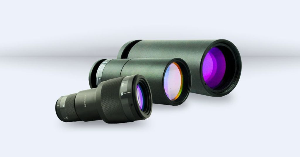
Before a beam ever reaches the scan lens, its diameter and divergence often need adjustment. Beam expanders resize the laser beam to match the input requirements of downstream optics, directly affecting focused spot size and depth of focus. Three configurations are typical:
- Fixed beam expanders offer a fixed magnification factor (commonly 1x–50x) with high transmissivity and anti-reflection coatings — ideal for applications that don’t require on-the-fly adjustment.
- Manual zoom beam expanders let operators continuously tune magnification to match changing process requirements without altering the housing length.
- Motorized zoom beam expanders automate that adjustment via RS232/USB control, enabling fast, repeatable magnification changes in automated production environments.
| Part Number | Wavelength (nm) | Magnification | Type | Input CA (mm) | Output CA (mm) | Mounting Thread | Max. Outer Dia (mm) | Total Length (mm) | Max. Input Beam Dia (1/e(2) (mm) |
|---|---|---|---|---|---|---|---|---|---|
| BEX-405-1.5X | 405 | 1.5X | Fixed | 8 | 26.0 | M30x1 | 46 | 62.3 | - |
| BEX-405-2X | 405 | 2X | Fixed | 8 | 26.0 | M30x1 | 46 | 62.3 | - |
| BEX-405-3X-V1 | 405 | 3X | Fixed | 8 | 18.0 | M22x0.75 | 28 | 52.5 | - |
| BEX-405-5X | 405 | 5X | Fixed | 8 | 28.0 | M30x1 | 46 | 78.0 | - |
| BEX-405-10X | 405 | 10X | Fixed | 9 | 28.0 | M30x1 | 46 | 85.6 | - |
| BEX-405-20X | 405 | 20X | Fixed | 6 | 31.0 | M30x1 | 46 | 77.0 | - |
| BEX-355-1X | 355 | 1X | Fixed | 15 | 18.0 | M30x1 | 36 | 61.0 | - |
| BEX-355-2X-V1 | 355 | 2X | Fixed | 8 | 28.0 | M30x1 | 46 | 82.0 | 7.0 |
| BEX-355-2X2 | 355 | 2X | Fixed | 6 | 23.0 | M22x0.75 | 33 | 57.0 | - |
| BEX-355-2.5X | 355 | 2.5X | Fixed | 12 | 23.4 | M30x1 | 36 | 61.0 | - |
| BEX-355-4X-V1 | 355 | 4X | Fixed | 8 | 28.0 | M30x1 | 46 | 82.0 | - |
| BEX-355-5X | 355 | 5X | Fixed | 6 | 28.0 | M30x1 | 46 | 73.5 | - |
| BEX-355-7X | 355 | 7X | Fixed | 6 | 28.0 | M30x1 | 46 | 88.1 | - |
| BEX-355-7X-D1 | 355 | 7X | Fixed | 4 | 9.6 | M14x0.5 | 16 | 54.0 | 1.0 |
| BEX-355-8X | 355 | 8X | Fixed | 6 | 28.0 | M30x1 | 46 | 84.0 | - |
| BEX-355-10X-D0.8 | 355 | 10X | Fixed | 8 | 18.0 | M22x0.75 | 28 | 71.5 | 0.8 |
| BEX-355-10X-D1 | 355 | 10X | Fixed | 4 | 13.6 | M18x0.5 | 20 | 50.0 | 1.0 |
| BEX-355-15X-D1 | 355 | 15X | Fixed | 4 | 19.0 | M24x0.5 | 27 | 69.0 | 1.0 |
| BEX-355-20X-V1 | 355 | 20X | Fixed | 10 | 28.0 | M30x1 | 46 | 97.0 | - |
| BEX-355-30X | 355 | 30X | Fixed | 8 | 36.0 | M30x1 | 45 | 173.0 | 1.0 |
| BEX-266-1.5X | 266 | 1.5X | Fixed | 8 | 24.0 | M22x0.75 | 30 | 63.7 | - |
| BEX-266-2X | 266 | 2X | Fixed | 8 | 24.0 | M22x0.75 | 30 | 73.0 | - |
| BEX-266-3X | 266 | 3X | Fixed | 10 | 23.0 | M22x0.75 | 30 | 68.7 | - |
| BEX-266-5X | 266 | 5X | Fixed | 10 | 23.0 | M22x0.75 | 30 | 69.6 | - |
| BEX-266-10X | 266 | 10X | Fixed | 6 | 23.0 | M22x0.75 | 30 | 95.6 | - |
| BEX-266-20X | 266 | 20X | Fixed | 1.5 | 30.0 | M22x0.75 | 30 | 96.0 | - |
| BXZ-355-1-3X | 355 | 1X - 3X | Manual Zoom | 23 | 38.0 | - | - | 131.0 | 6.0@1X 5.0@3X |
| BXZ-355-1-4X | 355 | 1X - 4X | Manual Zoom | 23 | 28.0 | - | - | 138.0 | 5.0@1X 4.0@4X |
| BXZ-355-1-8V | 355 | 1X - 8X | Manual Zoom | 12 | 33.0 | M51x0.75 | 54 | 162.0 | 3.5@1X 2.5@8X |
| BXZ-355-2-4X-G7 | 355 | 2X - 4X | Manual Zoom | 12 | 34.0 | - | - | 179.5 | 7.0@2X 6.0@4X |
| BXZ-355-2-8X-QA | 355 | 2X - 8X | Manual Zoom | 23 | 60.0 | - | - | 200.8 | 6.0@2X 4.0@8X |
| BXZ-355-2-10X | 355 | 2X - 10X | Manual Zoom | 23 | 35.0 | - | - | 172.0 | 8.0@2X 3.0@10X |
| BXZ-355-2-8X-G-V2 | 355 | 2X - 8X | Manual Zoom | 12 | 32.0 | M53x0.75 | 64 | 220.0 | 6.0@2X 2.5@8X |
| BXZ-266-1-7X | 266 | 1X - 7X | Manual Zoom | 23 | 32.0 | - | - | 191.8 | 5.0@1X 3.0@7X |
| BXZ-266-2-7X | 266 | 2X - 7X | Manual Zoom | 23 | 32.0 | - | - | 180.3 | 5.0@2X 3.0@7X |
| BXZ-257-1-5X-G4 | 257 | 1X -5X | Manual Zoom | 12 | 28.0 | M54x0.75 | 65 | 199.0 | 4.0 |
| BXZ-355-1-8X-MOT | 355 | 1X - 8X | Motorized Zoom | 23 | 32.0 | - | - | 136.0 | 4.0@1X 2.0@8X |
| BXZ-266-1-3X-G | 266 | 1 - 3X | Manual Zoom | 16 | 26.0 | M46x1 | 50 | 120.0 | 6.0@1X 3.0@4X |
| BXZ-266-1-7X-MOT | 266 | 1X - 7X | Motorized Zoom | 23 | 32.0 | - | - | 136.0 | 5.0@1X 3.0@7X |
| BXZ-257-1-5X-G4-MOT | 257 | 1X - 5X | Motorized Zoom | 12 | 28.0 | - | 50 | 207.0 | 7.0@1X 4.0@5X |
3.3 UV Laser Line Mirrors

High-reflectivity mirrors direct the UV beam through the optical path with minimal loss. These are typically optimized at specific Nd:YAG harmonic wavelengths and their fundamentals, engineered for high damage thresholds and excellent surface quality so that beam-guiding introduces negligible distortion or power loss — a small component with an outsized impact on overall system efficiency.
| Part Number | Wavelength (nm) | Dia (mm) | ET (mm) | Material | Reflectivity (%) |
|---|---|---|---|---|---|
| RFS-0.75-3.2U | 355 | 19.1 | 3.2 | Fused Silica | 99.5 |
| RFS-0.75-9.5U | 355 | 19.1 | 9.5 | Fused Silica | 99.5 |
| RFS-20-2U | 355 | 20.0 | 2.0 | Fused Silica | 99.5 |
| RFS-1-3U | 355 | 25.4 | 3.0 | Fused Silica | 99.5 |
| RFS-1-6U | 355 | 25.4 | 6.0 | Fused Silica | 99.5 |
| RFS-1-6.3U | 355 | 25.4 | 6.3 | Fused Silica | 99.5 |
| RFS-1-9.5U | 355 | 25.4 | 9.5 | Fused Silica | 99.5 |
| RFS-30-5U | 355 | 30.1 | 5.0 | Fused Silica | 99.5 |
| RFS-1.5-3U | 355 | 38.1 | 3.0 | Fused Silica | 99.5 |
| RFS-1.5-9.5U | 355 | 38.1 | 9.5 | Fused Silica | 99.5 |
| RFS-38.5-3U | 355 | 38.5 | 3.0 | Fused Silica | 99.5 |
| RFS-50-5U | 355 | 50.0 | 5.0 | Fused Silica | 99.5 |
| RFS-2-6.3U | 355 | 50.8 | 6.3 | Fused Silica | 99.5 |
| RFS-2-9.5U | 355 | 50.8 | 9.5 | Fused Silica | 99.5 |
| RFS-1-9.5V | 266 | 25.4 | 9.5 | Fused Silica | 99.5 |
| RFS-30-5V | 266 | 30.0 | 5.0 | Fused Silica | 99.5 |
| RFS-1.5-9.5V | 266 | 38.1 | 9.5 | Fused Silica | 99.5 |
| RFS-2-9.5V | 266 | 50.8 | 9.5 | Fused Silica | 99.5 |
4. Materials and Coatings
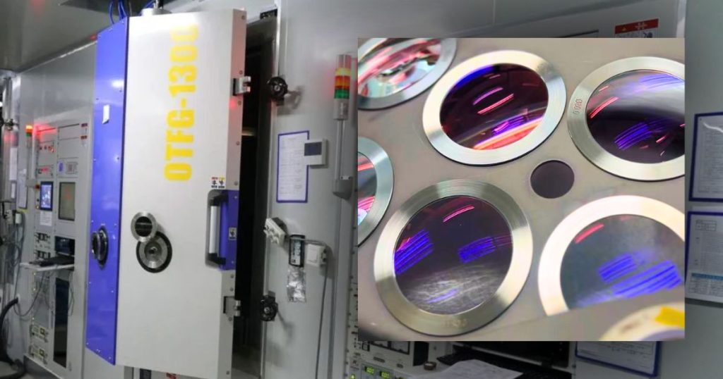
Behind every UV optic’s headline specification — focal length, magnification, reflectivity — sits a set of material and coating decisions that determine whether that specification holds up under real operating conditions.
Substrate choice. UV-grade fused silica is the default substrate for most UV laser optics because of its high transmission across the UV band and its resistance to laser-induced damage. Within fused silica itself, there are grades distinguished by hydroxyl (OH) content and metallic impurity levels, both of which affect UV transmission and damage threshold. For the most demanding deep-UV applications, even more specialized substrates such as calcium fluoride (CaF₂) may be required.
Anti-reflection (AR) coatings. AR coatings minimize reflective losses at each optical surface, but UV AR coatings must be engineered to resist solarization and maintain performance under sustained high-fluence exposure — a coating that performs well at visible wavelengths can degrade rapidly under UV illumination if it isn’t specifically designed for that band.
High-reflectivity (HR) coatings. For mirrors and beam-steering optics, HR coatings need to combine very high reflectivity (often 99%+) with a high laser-induced damage threshold (LIDT), since mirrors in a UV beam path are frequently the components most exposed to peak fluence, especially in pulsed systems.
Cleanliness and handling. UV photons carry enough energy to break down organic contaminants on an optical surface, so even trace hydrocarbon residue from handling or a poorly sealed housing can lead to laser-induced contamination and gradual performance loss. This is why UV laser optics are typically cleaned, coated, and packaged under stricter cleanroom protocols than IR or visible-light counterparts.
5. Why the Details Matter
A UV optical system is only as strong as its weakest component. A scan lens with excellent field flatness paired with a beam expander that introduces divergence error, or a mirror coating that degrades under repeated high-fluence exposure, will undermine the precision the rest of the system was designed to deliver. This is why UV laser optics selection is rarely a catalog-only exercise — matching lens focal length, scan field, working distance, input beam diameter, and coating specification to the actual laser source and application is what separates a system that performs from one that merely runs.
6. Choosing the Right UV Laser Optics for Your System
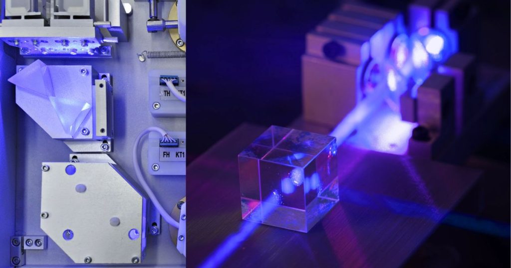
For engineers specifying UV laser optics, a few practical questions tend to drive the decision more than any single spec sheet number:
- What is the laser’s operating wavelength, and how tight is that band? Optics designed for 355 nm won’t perform optimally at 266 nm, even though both are “UV.” Coatings are wavelength-specific, and using an off-spec optic — even one that looks similar on paper — can introduce unexpected losses or a reduced damage threshold.
- What scan field and working distance does the application require? F-theta lens selection is driven directly by these two numbers, along with the input beam diameter from the laser source and any galvo scan head compatibility requirements.
- Is machine vision or inspection integrated into the process? If so, an achromatic or achromatic telecentric F-theta lens is often necessary to keep both the processing and imaging wavelengths in focus simultaneously.
- What’s the duty cycle and power level? High-repetition-rate or high-average-power systems place a premium on damage threshold and thermal stability, which affect both substrate and coating selection.
- Is there room for a catalog solution, or does the application require custom geometry? Standard scan fields and working distances are often met off the shelf; non-standard mechanical envelopes or unusual beam parameters typically require custom lens design.
Getting these decisions right before placing an order is far cheaper than discovering a mismatch after a system is built — which is where working with a supplier who can advise on the full optical chain, not just sell individual components, becomes valuable.
7. Where Wavelength Opto-Electronic Fits In
This is precisely the space Wavelength Opto-Electronic has built its UV laser optics portfolio around. As a Singapore-based precision optics manufacturer, Wavelength designs and manufactures the full chain of UV beam-delivery components — UV F-theta scan lenses (standard, telecentric, achromatic, and achromatic telecentric variants), fixed and zoom beam expanders (including motorized options), and high-damage-threshold UV laser line mirrors — engineered specifically for wavelengths spanning 193 nm through 405 nm.
A few things stand out about their approach:
Depth of catalog. Wavelength offers an extensive range of off-the-shelf F-theta lenses covering scan fields from just a few millimeters to over a meter square, across UV wavelengths including 193, 248, 257, 266, 355, and 405 nm — giving system integrators a strong starting point without a ground-up custom design cycle.
Compatibility-first design. Their scan lenses are built with adapters compatible with major galvanometer scan head manufacturers, reducing integration friction for OEMs and system builders.
Customization when the catalog isn’t enough. For applications with unique working distances, scan field geometries, or coating requirements, Wavelength supports full custom optics design, in-house optical coating, and system-level customization — meaning a non-standard requirement doesn’t have to mean starting from scratch with a new vendor.
High-power, precision-grade construction. Their beam expanders and laser line mirrors are built for demanding industrial and scientific environments, with pointing stability under 1 mrad and mirror damage thresholds suited to pulsed UV operation — the kind of specification that matters when a system runs continuously in production.
Applications breadth. From laser marking and engraving to laser cutting, drilling, welding, and scanning systems, Wavelength’s UV laser optics are positioned to support the full spectrum of UV laser material-processing applications, alongside their broader catalog of CO₂ optics, SWIR lenses, and imaging optics for adjacent system needs.
Engineering support, not just parts. Because UV laser optics selection is rarely a plug-and-play exercise, Wavelength’s engineering team works directly with customers to match lens focal length, scan field geometry, and coating specification to the actual laser source and application — the kind of consultative approach that helps avoid costly mismatches discovered only after a system is assembled.
A single source across the beam path. Rather than sourcing F-theta lenses from one vendor, beam expanders from another, and mirrors from a third — each with slightly different coating philosophies and quality standards — Wavelength’s ability to supply the full UV beam-delivery chain from one manufacturer simplifies both procurement and performance troubleshooting, since a single team understands how each component interacts with the others.
8. Industry Trends Shaping UV Laser Optics Demand
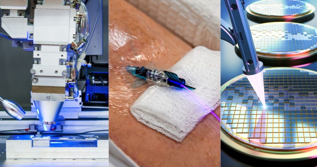
A few broader trends are pushing UV laser optics further into the mainstream of precision manufacturing, and they’re worth keeping in mind for anyone planning a system’s optical requirements over the next several years:
- Miniaturization in electronics. As consumer electronics, semiconductors, and PCBs pack more functionality into smaller footprints, the fine feature sizes achievable with UV wavelengths are becoming less of a luxury and more of a baseline requirement.
- Green manufacturing pressure. UV laser processes often produce less waste and require fewer chemical treatment steps than traditional subtractive or etching processes, aligning with sustainability goals across electronics and medical device manufacturing.
- Automation and Industry 4.0 integration. Motorized beam expanders and vision-integrated F-theta systems reflect a broader shift toward laser systems that can self-adjust and self-monitor within automated production lines, reducing manual recalibration.
- Medical device miniaturization. Stent cutting, microfluidic fabrication, and other precision medical applications increasingly rely on UV laser processing, driving demand for optics with tighter tolerances.
9. The Takeaway
UV laser optics don’t get the same spotlight as the laser source itself, but they’re the components that translate raw laser output into usable, precise, repeatable results. Whether you’re specifying a marking system, building a semiconductor inspection tool, or designing a custom laser-material-processing line, the F-theta lens, beam expander, and mirror choices you make will shape your system’s real-world performance as much as the laser itself.
For teams evaluating UV laser optics — whether sourcing standard components or working through a non-standard requirement — Wavelength Opto-Electronic’s combination of broad catalog depth, integration-friendly design, and in-house custom optics capability makes us a strong starting point for an RFQ. Our team offers direct consultation on matching lens and beam-expander specifications to your laser source and application, which is often the fastest way to avoid costly trial-and-error in system design.
